How to Verify Chemical Compatibility for New Valve Materials
Engineers can validate chemical compatibility by mapping process conditions, checking material data, reviewing vendor certificates, and performing witness tests before installation. This method reduces the risk of premature valve failure in aggressive fluid services.
- Chemical compatibility depends on temperature, pressure, flow velocity, and impurities, not just the primary fluid.
- Always verify material grades with mill certificates and confirm gasket and trim compatibility.
- Use witness tests or small sample exposure when field conditions cannot be fully simulated in a lab.
- Document all assumptions and test results to support future maintenance and replacement decisions.
Why Chemical Compatibility Checks Fail in the Field
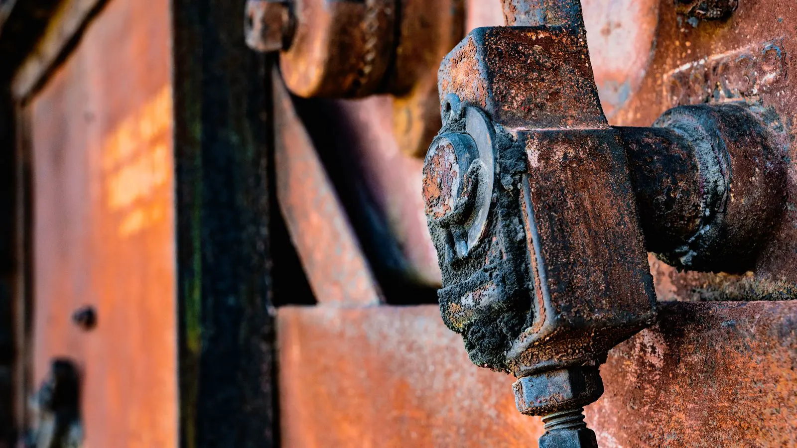
Engineers often assume that a selected material will handle a process stream if it has worked in a similar application. In practice, that assumption breaks down when temperature, impurities, or flow patterns shift. A stainless steel valve body may pass a routine visual inspection yet suffer pitting at a weld seam after a few months of service. The failure starts before installation. It begins when the material selection is treated as a static choice instead of a dynamic validation process.
This guide outlines a step-by-step method to verify chemical compatibility for new valve materials. The approach works for carbon steel, stainless steel, and exotic alloy valves. It assumes you have access to process data, supplier documentation, and a basic understanding of corrosion mechanisms. If any of these inputs are missing, stop and gather them before proceeding.
Step 1: Map the Exact Process Conditions
Before selecting or confirming a material, define the operating envelope. Record the primary fluid name, concentration, temperature range, pressure, and flow velocity. Include the startup and shutdown conditions, as these often create the most severe stress. For example, a valve that sits idle in a concentrated acid solution may corrode faster than one in continuous flow.
Create a table that lists each condition. If the process involves multiple phases, such as gas and liquid, specify the interface conditions. Do not rely on average values. Use worst-case scenarios for verification. This step protects you against surprises during commissioning.
| Condition | Typical Value Range | Why It Matters |
|---|---|---|
| Temperature | Ambient to 400°C | Affects reaction rates and phase changes |
| Pressure | 0 to 100 bar | Influences dissolved gas concentration |
| Flow Velocity | 0.5 to 5 m/s | Changes erosion-corrosion risk |
| Fluid Concentration | 0 to 100% | Determines corrosion potential |
| Impurities | Trace to significant | Chlorides and sulfides accelerate attacks |
Step 2: Review Material Specifications and Certifications
Once the conditions are mapped, check the material specifications provided by the supplier. Look for mill test certificates that confirm the actual chemical composition. Nominal grades can vary. A 316L stainless steel valve might contain higher molybdenum than expected, or it might have carbon levels that affect weld strength.
Verify that the heat treatment matches the required condition. For example, a solution-annealed stainless steel valve performs differently than one that has been cold-formed without annealing. Also, confirm that the material specification aligns with the intended service. If the fluid contains chlorides, a standard 316L grade may not be sufficient. You might need a higher grade with more molybdenum or a duplex alloy.
Do not accept generic material declarations. Request specific certificates for each lot of material used in the valve. If the supplier cannot provide detailed documentation, treat the material as unverified and consider alternative sources.
Step 3: Assess Gasket and Trim Compatibility
The valve body is only part of the system. The gaskets, seats, and stems are often the first components to fail in aggressive service. A stainless steel valve body may be perfectly compatible with the fluid, but the PTFE gasket may degrade under high heat or the elastomer seat may swell in organic solvents.
Check the gasket material against the process conditions. For example, a nitrile rubber gasket may handle mild acids but fail in ketones. A PTFE gasket offers broad chemical resistance but has lower pressure limits. The trim material, often the same as the body or a different grade, must also be verified. In some applications, the trim is harder than the body to prevent wear, but this difference can create galvanic issues if the fluid is conductive.
Create a separate compatibility check for each non-metallic part. Do not assume that a “chemical resistant” gasket is suitable for every condition. Review the manufacturer’s chemical resistance charts for specific temperatures and concentrations.
Step 4: Consult Standard Charts and Engineering Data
Use recognized corrosion charts and engineering data to cross-check your findings. These resources provide general guidance on material resistance to common chemicals. They are useful for identifying obvious mismatches. For instance, a chart might show that carbon steel is unsuitable for dilute sulfuric acid above a certain temperature.
However, charts provide general trends, not guarantees. They do not account for flow velocity, impurities, or specific alloy compositions. Use them as a first-pass filter. If the chart indicates a high risk, stop and investigate further. If the chart shows a low risk, proceed to the next step. Do not rely solely on a chart for a final decision.
Keep a reference file of the charts you use. Note the date of the data source. Corrosion behavior can be misunderstood if outdated data is applied to modern alloy formulations.
Step 5: Perform Witness Tests or Sample Exposure
When process conditions are unique or the material is new to the application, conduct a witness test. This involves exposing a small sample of the valve material to the actual process fluid under controlled conditions. The test should replicate the temperature, pressure, and flow velocity of the real application.
The test duration depends on the expected service life. A short test of a few days may reveal rapid corrosion, but it will not show slow degradation over years. For critical applications, run the test for a period that reflects a fraction of the anticipated service life. Measure the material loss using calipers or weight loss methods. Record any visual changes, such as pitting, stress corrosion cracking, or discoloration.
If a full witness test is not possible, use a smaller scale exposure. Place a coupon of the valve material in a sealed container with the process fluid. Keep it in the same environment as the valve will experience. After the test, clean the coupon and inspect it under a magnifying lens. Document the results with photographs and measurements.
Step 6: Verify Installation and Maintenance Practices
Chemical compatibility is not just about material selection. It is also about how the valve is installed and maintained. A perfectly compatible valve can fail if it is installed in a way that creates stagnant zones or thermal stresses. For example, if a valve is installed in a horizontal line with a low point, liquid may accumulate and concentrate impurities. This can accelerate local corrosion.
Check the installation drawing. Ensure that the valve is oriented correctly for the fluid type. For gas service, the bonnet should be installed at the high point to prevent condensation. For liquid service, the bonnet may need to be at the low point to avoid air pockets. Also, verify that the supports and piping do not create thermal stress on the valve body.
Plan for maintenance. If the valve will be taken offline for cleaning, define the procedure. Residual chemicals can continue to corrode the material even when the valve is not in service. Flush the line thoroughly before storage. If the valve will be exposed to the atmosphere during maintenance, consider protective coatings or temporary covers.
Step 7: Document the Verification Process
Keep a record of every step in the verification process. Include the process data, material certificates, chart references, test results, and installation notes. This documentation serves as a baseline for future maintenance. If the valve fails after a few years, the records will help identify whether the material was unsuitable or if an external factor caused the issue.
Store the records with the valve data sheet. Include copies of the mill certificates and test reports. If the process changes in the future, refer back to these records to see if the new conditions fall within the verified envelope. If they do not, repeat the verification process for the updated conditions.
This documentation step is often overlooked. It is the difference between a reactive maintenance approach and a proactive one. It also supports liability and insurance claims if a failure occurs.
Common Mistakes to Avoid
Engineers frequently make errors that undermine chemical compatibility verification. One common mistake is relying on a single data point. A material may perform well at room temperature but fail at elevated temperatures. Always verify across the full operating range.
Another mistake is ignoring the impact of impurities. A fluid that is nominally pure may contain trace chlorides or sulfides that drastically change the corrosion behavior. Test the actual fluid, not a representative sample from a different source.
Do not skip the gasket and trim check. The body may be fine, but the seal may fail. This is one of the most frequent causes of valve leaks in chemical service.
Finally, avoid assuming that a new material is always better. Sometimes a simpler material with a proven track record is more reliable than a high-performance alloy that has not been tested in your specific application. Choose based on evidence, not marketing claims.
Final Verification Step
Before approving the valve for installation, conduct a final review. Confirm that all steps have been completed. Check that the material certificates match the installed valve. Verify that the gasket and trim materials are compatible with the process conditions. Review the witness test results and ensure they are within acceptable limits.
Sign off on the verification record. Include the date, the name of the person responsible, and any conditions or limitations. For example, note that the material is verified for temperatures up to 150°C and pressures up to 20 bar. If the process changes, the verification must be repeated.
This final step closes the loop. It ensures that the valve is not just selected on paper, but validated for the specific application. It reduces the risk of early failure and supports long-term reliability.
When to Escalate the Verification
Some applications require more than the standard steps. If the fluid contains unknown impurities, or if the temperature exceeds 400°C, escalate the verification. In these cases, consult a corrosion specialist or a materials engineer. They can provide insights that are not available in standard charts or supplier data.
Escalation is also needed if the valve is in a safety-critical application. In such cases, the cost of failure is high. Use the most rigorous testing available. If the material is new to the company, consider a pilot run before full-scale installation.
Do not skip this step. The risk of a major leak or catastrophic failure outweighs the cost of additional testing. A small investment in verification can prevent a large loss in production.
References and Further Reading
For more detailed information, refer to the site’s other articles on material selection. The article on alloy selection and gasket life explains how the body material affects seal performance. The buyers guide on aggressive fluids provides context for selecting materials in severe service. The comparison of 316L and 2205 grades helps engineers understand trade-offs in corrosion resistance. The checklist for high-temperature chemical service offers a practical tool for verifying valves in extreme conditions.
These resources complement this guide. Use them to deepen your understanding of the factors that influence chemical compatibility. The goal is not just to verify the material, but to understand why it will or will not perform in your application.
Frequently asked questions
Can I use a generic chemical resistance chart to verify a new valve material?
No. Charts provide general trends but do not account for specific impurities, flow velocity, or temperature extremes. Use them as a first pass, then confirm with process-specific data and testing.
How long should a witness test run?
The duration depends on the expected service life. For critical applications, run the test for a period that reflects a fraction of the anticipated life. Short tests may reveal rapid corrosion but not slow degradation.
What if the supplier cannot provide mill test certificates?
Treat the material as unverified. Request specific certificates for each lot. If the supplier cannot provide documentation, consider alternative sources or perform independent material analysis.
Is the gasket material always compatible if the body material is?
No. Gaskets and seats have different chemical resistance limits. A stainless steel body may handle a fluid, but the PTFE or elastomer gasket may degrade under high heat or specific solvents. Check each non-metallic part separately.
Do I need to re-verify the valve if the process conditions change?
Yes. If the temperature, pressure, or fluid composition changes, the original verification may no longer be valid. Repeat the verification process for the new conditions and update the documentation.